Need any help or advice?![]() +44 (0)1782 454499
+44 (0)1782 454499
PRODUCTS USED IN THIS PROJECT
Although not necessarily an exhaustive list, the following tools and materials, supplied by Easy Composites, were used in this project.
The quantity shown below is the approximate amount used in the project rounded up to the nearest available kit size or quantity.
MATERIALS & CONSUMABLES

TOOLS & EQUIPMENT

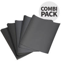
REINFORCEMENTS
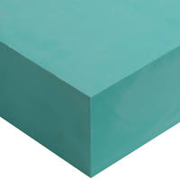
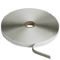
MOULD MAKING MATERIALS
VIDEO TUTORIAL
How to Make a Carbon Fibre Bike Frame From Start to Finish
In depth technical interview with bike designer and composites enthusiast Vlad Yordinov discussing and explaining the process of making a production quality, race-ready carbon fibre frame for a downhill mountain bike, from original CAD design through to final fit-out.
In this 40min video Vlad shows us how he turned his original design into a finished bike without the need for the investment in hugely expensive billet aluminium tools that are generally used by the large manufacturers to make carbon fibre bike frames. By using much less expensive composite tools and curing the laminate under vacuum pressure rather than positive pressure from an inflatable bladder, Vlad is able to produce a high performance bike frame for less than a 1/10 of the typical cost to produce even a prototype carbon bike frame.
TUTORIAL BREAKDOWN
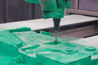
1. Patterns machined from tooling board
Once the design of the frame and the pattern has been decided on, it can then be machined from tooling board. For this process, epoxy tooling board is used as it has the properties necessary to allow it to be used in the production of carbon fibre tooling using a specialist tooling pre-preg.
The board itself is machined in a 3 axis machine. In this case the design is such that only a 3 axis machine is required to do the shape and detail. A 5 axis machine may be needed for more complex projects.
The machine cuts the board in several stages, starting with a very rough cut before repeating the passes with finer and finer cuts until the pattern is fully machined from the block. However, the finish from the machining process will need further hand fettling and sealing to get it high enough quality for the moulding process.
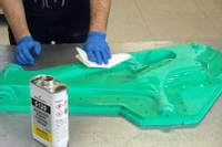
2. Finishing and sealing the patterns
Post machining, the pattern will need smoothing out by sanding the surface until the desired finish is achieved. The pattern then needs sealing to give a gloss sealed surface ready to mould from.
Multiple coats of sealant are used on the main part of the pattern to get the high quality, high gloss finish. Typically only 2 layers of sealant is used on the flanges - this is to ensure that when clamping the mould together, there is a very high level of accuracy and precision on the mating surfaces.
Due to the frame complexity, it is necessary to use inserts onto the mould to ensure that under cuts and certain complex detail is formed correctly. These areas also have precision accuracy requirements so should only have a couple of layers.
Holes have been drilled into the mould to allow metal alignment inserts to be fitted. This is to ensure that once the moulds are made, they are perfectly aligned so that the holes can be used to bolt the mould halves together in precisely the right position. The holes are positioned as close as practical to the tooling part edge so that the clamping force around the critical joining areas is consistent.
3. Making the female moulds
The mould is being made from the XPREG XT135 Tooling pre-preg system. This comprises of a surface layer and a backing layer. In this case one layer of surface ply is used and then the surface ply was backed up with 5 layers of backing ply to give a good strong and stiff mould.
To aid getting the surface ply into the difficult corners and tightly around the pins, strips of surface ply with the fibres orientated at 45 degrees are used in those difficult areas. The rest of the surface layer is then built up. In this case, due to the complex shape and accuracy critical nature of the mould process, the mould was debulked by placing it into a vacuum bag with a perforated release film and a vacuum pulled on it. This helps get all the pre-preg material into the tight corners.
The backing layers are then built up until all 5 layers are done. Regular debulking helps fibre consolidation as well as ensuring there are going to be no voids in the lay up.
The mould is now ready to be cured and is vacuum bagged and cured at 60°C for the initial low temperature cure cycle. The reason it is not cured on the pattern at higher temperature is that epoxy tooling block will expand slightly at higher temperature which will induce more dimensional inaccuracy.
At this stage, the mould is demoulded from the pattern. The Tooling block generally comes out fairly easily. However, the pins are tightly in and need care and time to remove. Grips can be used to pull them out, but a good technique in this case was spinning and winding them out using a drill.
This same process is repeated for the second half of the mould. Once both halves have been demoulded and trimmed, they are ready to be post cured. The post cure finishes off the cure of the mould itself and ensures it can be used at the high curing temperature of the pre-preg for the finished part. In this case, as it is a split mould, both halves are bolted together for the post cure. This is to ensure that the mounting faces will end up perfectly aligned and not under undue stress when bolted together in use.
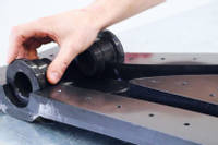
4. Mould inserts
Mould inserts are necessary in certain areas such as where the frame splits . The insert allows the area around the split to be fully moulded correctly as one part. Also the inserts aid overall demoulding in such complex areas of the frame.
Similar to the main mould, a pattern for the insert is machined from tooling block. An addition cure silicone is then used to take a mould from the pattern. Once cured, the mould can be easily released from the pattern and is now ready to make the insert.
The insert is cast from high temperature epoxy and milled carbon/graphite powder. This adds strength to the insert and, by having a large amount of carbon in the insert, means that the insert will have a similar CTE to the carbon mould meaning they will expand and contract similarly during the curing process.
The cast insert needs smoothing and surface sealing with the S120 to give a polished high gloss finish. It is then release coated and ready to be used. One advantage of using inserts cast from a silicone mould is that if it is necessary, the insert can be broken or destroyed during demoulding to save the frame, yet be quickly recast using the silicone mould.
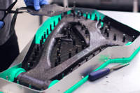
5. Laminating the frame
The frame layup for this design uses a mix of woven twill pre-preg fabrics and Uni-directional pre-preg fabrics. The first stage is preparing templates for the surface layer of woven pre-preg. This is templated by hand and is critical to get the fibre orientation matching between moulds and sections within each mould as it is a visible cosmetic layer.
Two woven layers are laid into the moulds, the first layer orientated as per the templates. The moulds are then debulked prior to applying the second layer. The second layer is orientated at 45° to add torsional and twist strength.
Templates for the UD pre-preg are made and the pre-preg is cut out all in one go. There are over 200 pieces of pre-preg fabric in a frame of this size. The UD cloth adds a lot of strength in the direction the fibres are orientated. As this frame has hoop and torsional strength from the woven plies, the majority of the UD fabric in the main tubes is aligned along the tubes length to provide stiffness down the tubes length. The UD orientation is rotated around mounts and brackets in the specific directions the forces will end up in those areas. Overall on a frame like this, the main tubes will have 2 woven surface plies, 4 UD plies and a final inner woven ply. Being the prototype frame, it is likely that post testing, the number of plies will likely be reduced in many areas for subsequently produced frames.
In structurally critical areas, extra plies of material are used for added strength as well as the orientation being varied to suit the load paths. eg around many of the pins, the UD fabric is rotated around so when demoulded and used, the hole area is very strong as there are no cut fibres around the hole itself. Specific layup consideration is needed around the many inserts both for the stength and loads those areas will take and also the processing of the part. Some areas are inaccessible for vacuum bagging so rely on the compression of the insert and mould to consolidate the fibres properly.
Lap joints are created on the moulds. This is done so when the moulds are joined together, there is sufficient strength in the areas where the frame is joined together. The lap is tapered across its width and multiple layers to ensure the overlapping joint retains its strength throughout. Finally at this stage, some of the final inserts are laminated and fitted into place.
6. Internal vacuum bags
In large scale production, typically a bladder would be used for this stage, however the bladders are specially produced and require the use of expensive billet tooling. For low volume production, the use of vacuum bags is more achievable.
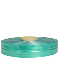
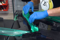
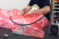
Tubular vacuum bagging film is measured and cut to size. One end of each tube is then heat sealed to make it air tight at that end. When using this bagging film it is necessary to apply release film to one part of the mould. This is so that, when the vacuum is pulled, the bagging film is free to slip and slide over the surface as it expands and presses over the mould surface. Care needs to be taken to trim the release film so that none of it accidentally can end up over the lap joint faces which could cause bonding issues and a weak point on the frame. For this reason only the side with laps has the film applied.
The bag is carefully laid into each tube ensuring there is enough excess for it to expand properly. In areas where the ends of the bag meet, there is a little bit of overlap so that when the vacuum is pulled, every part of the mould has the bag.
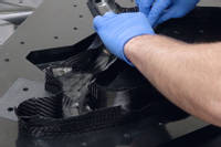
7. Closing the moulds
This stage is critical as any misaligned laps or trapped bagging tube could ruin the whole project. The laps and bag needs to be folded in as best you can to ensure no material is on the flange.
The mould is held with a small gap so that you can look through the gap to ensure no material is trapped, Using a flat tool, it is possible to manipulate any material that needs moving slightly. The mould is then fully closed.
The 2 mould halves are aligned through the use of pins spaced around the mould. The two halves are then bolted together.
8. External vacuum bag
At this stage the entire mould is to be placed into a Vacuum Bag, The 4 pieces of tubular bag will need to go through the seal on the main vacuum bag. This is so that the inside of the tubular bags are open to atmosphere so that, when a vacuum is pulled on the main bag, the tubular film is forced by atmospheric pressure against the inside of the tubes inside the mould.
Once the bag has been sealed, a vacuum can be pulled on the bag. Care needs to be taken to ensure the bagging film gets into all the right corners on the mould outside and that there are no bridges in the film. Once done a leak test will need to be carried out to ensure the bag is properly sealed. The bag is then left to debulk overnight. Once the debulk has been successfully carried out, the mould is ready to be cured in the oven.
9. Oven cure and demould
Being made with XPREG XC110, the standard extended cure cycle is being used for the oven cure. The bag is connected to the vacuum through out the cure and then the cycle is run on the part. Once fully cured and cooled, it is ready to be demoulded.
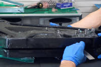
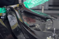
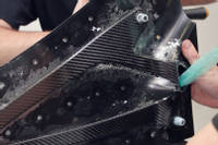
To demould, the bag is stripped off the mould and the bolts holding each halve together removed. The locking pins are tapped out and then, using demoulding wedges, the two halves are slowly separated. At this point the bike frame can be carefully removed from the mould.
At this point the inserts are removed. They relatively easily tap out, taking advantage of the draught angles on the frame design to easily release. The frame is then ready for inspection and for the flash lines and edges to be trimmed prior to painting and final assembly.
10. The rear triangle
The basic method and techniques used for the rear triangle are basically identical to that of the main part of the frame. The main difference is the lay up of the pre-preg which is different to the frame with more of the UD towards the outside of the tube. The smaller size means that the lap joints have been designed so that once cured, the layup will be even.
The same bagging process using the main vacuum bag and tubular bagging film is done with the same cure cycle. In this case, the rear triangle is made from 2 pieces.
Once cured, the rear triangles are deburred and trimmed ready to be bonded together. For a application like this, the VM100 Black methacrylate adhesive is perfect as a structural adhesive. As this is a prototype frame, there is no jig yet so the frame is assembled so that the rear triangles can be bolted together to ensure proper alignment as the adhesive joint cures.
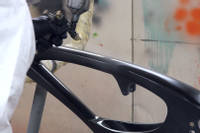
11. Finishing and paint
At this stage, the main composite work is done. The frame is now finished off with a light sand and fettle before spraying with a satin lacquer. In this case, no other paint is used as we wanted to show off the raw carbon finish under the clear lacquer.
The frame can then be assembled with all the bearings, linkages, brackets and parts to make a finished bike. It was then tested and raced with the feedback used to tweak the design and layup ready for the production model.
DISCUSSION (24)
Please share any questions or comments you may have about this video tutorial.
Carbon fibre bike frames are extremely complex components to make with lots of narrow tube sections, tight details and precisely placed inserts. The complexity of the layup means that laminating into a mould, in the way shown in this video, can only really be done using prepreg, which can be cut and placed accurately without any time pressure. It would be pretty-much impossible to do the same thing by hand laminating dry fibre and wet epoxy resin (in multiple layers), into the two mould halves - with overlaps - around pre-made vacuum bag tubes and then close the two moulds together before pulling the vacuum and curing.
If you are looking for a hand layup method of making a bike frame, a more realistic option would be to produce an accurately shaped foam core and then laminate carbon fibre and resin onto the outside of the foam core. This could then be wrapped in a shrink tape to consolidate the fibre or potentially vacuum bagged. Such a process is obviously not without its compromises (the core would stay inside the frame, the accuracy of the frame and finish would come down to a lot of hand-working on the outside of the laminate etc.) but it would be more realistic than trying to wet-lay then vacuum bag such a complex and inaccessible component.
Generally around 20% by weight of graphite and 20% by weight milled carbon will be about as much as you can get into the mix before it becomes too thick to pour properly.
LEAVE A COMMENT OR QUESTION
PRODUCTS USED IN THIS PROJECT
Although not necessarily an exhaustive list, the following tools and materials, supplied by Easy Composites, were used in this project.
The quantity shown below is the approximate amount used in the project rounded up to the nearest available kit size or quantity.
MATERIALS & CONSUMABLES
TOOLS & EQUIPMENT
REINFORCEMENTS
MOULD MAKING MATERIALS
DISCUSSION (24)
Please share any questions or comments you may have about this video tutorial.
Carbon fibre bike frames are extremely complex components to make with lots of narrow tube sections, tight details and precisely placed inserts. The complexity of the layup means that laminating into a mould, in the way shown in this video, can only really be done using prepreg, which can be cut and placed accurately without any time pressure. It would be pretty-much impossible to do the same thing by hand laminating dry fibre and wet epoxy resin (in multiple layers), into the two mould halves - with overlaps - around pre-made vacuum bag tubes and then close the two moulds together before pulling the vacuum and curing.
If you are looking for a hand layup method of making a bike frame, a more realistic option would be to produce an accurately shaped foam core and then laminate carbon fibre and resin onto the outside of the foam core. This could then be wrapped in a shrink tape to consolidate the fibre or potentially vacuum bagged. Such a process is obviously not without its compromises (the core would stay inside the frame, the accuracy of the frame and finish would come down to a lot of hand-working on the outside of the laminate etc.) but it would be more realistic than trying to wet-lay then vacuum bag such a complex and inaccessible component.
Generally around 20% by weight of graphite and 20% by weight milled carbon will be about as much as you can get into the mix before it becomes too thick to pour properly.
LEAVE A COMMENT OR QUESTION
100% SECURE
PAYMENT METHODS


Easy Composites Ltd, registered in England 7486797. All content copyright (C) Easy Composites Ltd, 2025. All rights reserved.