Need any help or advice?+44 (0)1782 454499

VIDEO TUTORIAL

USED IN THIS PROJECT

Although not necessarily an exhaustive list, the following tools and materials, supplied by Easy Composites, were used in this project.

The quantity shown below is the approximate amount used in the project rounded up to the nearest available kit size or quantity.

MATERIALS & CONSUMABLES
XC110 210g 2x2 Twill 3k Prepreg Carbon Fibre (1250mm) 1m Roll Thumbnail
XC110-C331T2-210(1250)-1XC110 210g 2x2 Twill 3k Prepreg Carbon Fibre (1250mm) 1m Roll£73.16 /roll

ST150 Vacuum Bagging Sealant Tape 15m Each Thumbnail
VBST150ST150 Vacuum Bagging Sealant Tape 15m Each£5.50 /roll

BR180 140g Breather Cloth (1520mm) 5m Folded Pack Thumbnail
AFBR180-152-5PKBR180 140g Breather Cloth (1520mm) 5m Folded Pack£9.75 /pack

VB160 Vacuum Bagging Film LFT (1520mm) 5m Folded Pack Thumbnail
AFVB160-152LFT-5PKVB160 Vacuum Bagging Film LFT (1520mm) 5m Folded Pack£12.40 /pack

VB155 Vacuum Bagging Film 100mm Tube - 5lm Folded Pack Thumbnail
AFVB155-010LFT-5PKVB155 Vacuum Bagging Film 100mm Tube - 5lm Folded Pack£4.95 /pack

Total £0.00
TOOLS & EQUIPMENT
OV301 Precision Composites Curing Oven Thumbnail
OVEN301OV301 Precision Composites Curing Oven£1749.00 /each

Plastic Demoulding Wedge Small Thumbnail
PA-W-SPlastic Demoulding Wedge Small£1.50 /each

Total £0.00

VIDEO TUTORIAL

Laminating and Bagging a Carbon Fibre Tube Using a Split Mould

In this video tutorial we take a detailed look at how to laminate and then vacuum bag tubular composite components using a split-mould process with an internal vacuum bag.

This process can be used to produce non-straight tube forms such as carbon fibre handlebars, kayak paddles and induction tubes. It can also be used for very complex tubular structures such as carbon fibre bike frames and suspension wishbones. In fact, this video is intended to provide a more detailed look at the laminating methodology and vacuum bagging principles used in our video tutorial on how to make a carbon fibre bike frame.

In situations where only a straight tube form is required, the roll-wrapped tube manufacturing method would often be more appropriate, or in commercial manufacture processes such as pultrusion or pulwinding, can also be used. However, none of these processes can be used for curved/bent tubes or complex tubular structures.


BACKGROUND

What about internal bladders?

This method is an alternative to the internal pressurised bladder method often used in bike frame production which requires much more substantial moulds, usually machined from solid billets of aluminium, which need to resist the deformation caused by the unbalanced pressure of the internal bladder.

By exerting pressure equally on the inside and outside of the mould, this internal vacuum bagging method causes little or no distortion of the mould, allowing much lighter – and lower cost – moulds to be used.

What about autoclave curing?

Although in this tutorial we demonstrate the process using only vacuum pressure with the component then cured in a conventional oven (known as out-of-autoclave prepreg), the exact same process can be - and is - used for high pressure curing of tube and frame structures in an autoclave. For autoclave curing, there would be no need to change any of the materials, layup or vacuum bagging process shown in this tutorial.

In common with the vacuum only out-of-autoclave cure, autoclave curing using this same internal vacuum bag configuration also creates equal pressure on both sides of the mould, allowing these lighter weight composite tools to be used.

Does it have to be prepreg?

Making complex carbon fibre tube or frame mouldings is almost exclusively done using the prepreg moulding process. The reason for this is mainly due to the practicalities of accurately cutting, handling and positioning the reinforcement within the split mould, manipulating this reinforcement when the mould is closed up and then working around the reinforcement to position the vacuum bagging consumables. All of these processes would be difficult or almost impossible if attempted using a traditional wet-layup method or alternative vacuum moulding processes such as resin infusion of dry fabric.

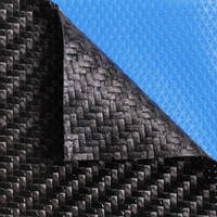
In this video we use the XPREG XC110 out-of-autoclave carbon fibre prepreg, oven cured using a ramped temperature profile up to 120C; video tutorial on making prepreg carbon fibre parts out-of-autoclave here.

Suitable tool/mould materials

Because this tutorial uses prepreg carbon fibre reinforcement, the component must be cured in an oven at elevated temperature. It is therefore essential that the material the mould is made from has a sufficiently high service temperature. The mould used in this tutorial was made using our XT135 out-of-autoclave carbon fibre tooling prepreg system; video tutorial on making prepreg carbon fibre tools out-of-autoclave here.

Alternatively, the mould could be hand-laminated using a high temperature epoxy tooling system, such as our EG160/EL160/EMP160 products; video tutorial on hand laminating a high temperature epoxy mould here.


TUTORIAL BREAKDOWN

Templating and cutting the first ply of prepreg

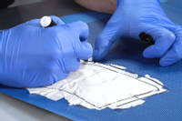
1. Templating and cutting the first ply of prepreg

To get an approximate shape to cut the prepreg reinforcement to, masking tape is applied onto the surface of one half of the split-mould. The masking tape is then removed and then positioned onto the prepreg reinforcement. Because the template won't yet be accurate, it is extended by about 1cm in all directions.

The rough-shape prepreg is then laminated into the mould. Once it's fully in place, any overhanging reinforcement is then carefully cut off to leave the reinforcement cut exactly to size, flush with the edge of the split.

The offcuts of carbon fibre are then put back onto the backing paper so that the paper can be cut to create a precise template that allows exactly for how the reinforcement drapes into the mould. This template can be retained for future use.

Templating the staggered laps

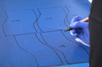
2. Templating the staggered laps

When laminating reinforcement into a split-mould, it is essential that most of the reinforcement continues over the split-line, avoiding a weak point at this join. Without overlapping any reinforcement, the two halves of the component would simply fall apart from each other!

Layers of reinforcement that continue over the split-line are call the overlaps, or 'laps'. To avoid creating other weak-points in the laminate, these laps themselves are staggered by making them different sizes. In the tutorial, the overlapping pieces of reinforcement are cut to 5mm, 10mm and 15mm wider than the split-line.

To try to maintain a consistent wall-thickness around the tube, the corresponding pieces of reinforcement for the other half of the tube are cut narrower than the split line. However, in order to create some overlap of the overlaps, the reinforcement on this shorter side is in fact cut slightly larger than it would be if the reinforcement was to meet in a perfect butt-join.

Adding the 'lapped' plies

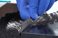
3. Adding the 'lapped' plies

The 'oversized' plies are laminated into the opposite side of the split-mould, in sequence.

The first ply to be added has the smallest (5mm) extension, designed to slightly overlap the cut-to-size first ply in the other side of the split-mould. Next the 10mm and 15mm extension plies are added.

Returning to the first side of the split-mould (which already has the cut-to-size ply in it) the two shorter plies are added to this half, again in sequence getting progressively shorter to match the progressively longer overlaps on the extension side.

Adding the tubular bagging film

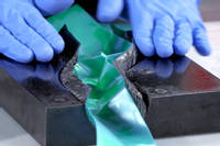
4. Adding the tubular bagging film

The vacuum bagging configuration in this tutorial is an internal tubular vacuum bag. This involves running length of tubular bag through the middle tube split mould and then linking this tube up to an external 'envelope' bag on the outside of the mould.

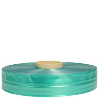
The type of tubular bagging film we use is our VB155 self-releasing, gusseted tubular bagging film in a 100mm width.

With the tubular bagging film inside, the two halves of the mould are carefully brought together, paying attention to ensure that the 'laps' are correctly positioned and do not get folded or trapped as the mould is closed.

Completing the vacuum bag

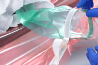
5. Completing the vacuum bag

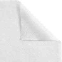
To begin with, the outside of the split mould is wrapped in BR180 breather cloth to provide an airflow path and prevent any accidental puncturing of the vacuum bag by any sharp details on the mould.

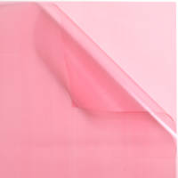
Next, the entire mould will be surrounded by a large 'envelope' bag of VB160 vacuum bagging film. The principle is that the tubular vacuum bag will create a 'tunnel' through the middle of the envelope bag. When the vacuum is pulled it will be pulled from inside the envelope bag, sucking the bag down onto the outside of the mould and the tubular bag onto the inside of the tube.

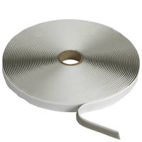
To create this 'tunnel' through the bag, the outside of the tubular bag is sealed to the inside of the envelope bag using some vacuum bagging sealant tape.

A full vacuum is then pulled on the vacuum bag using our EC.4 composites vacuum pump. Careful checking is undertaken to ensure that the vacuum bag is perfectly sealed with no leaks.

Oven cure the prepreg

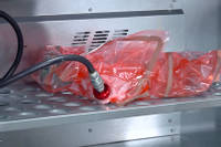
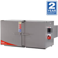
6. Oven cure the prepreg

The vacuum bagged part is then transferred to an oven to cure. Because we're using the XPREG XC110 out-of-autoclave prepreg to make this component then a specific cure cycle needs to be followed in order to get the best results. See the XC110 processing guide for full details on recommended cure cycles and processing for XPREG XC110.


DISCUSSION (19)

Please share any questions or comments you may have about this video tutorial.


ingusmant
There seems like a lot of waste with the vacuum forming process, is there any alternatives?
Easy CompositesMatt
It depends what you need to achieve. For low volume production, there's not really much you could do to reduce consumables if you want to achieve a high quality product but if you were making hundreds (or thousands) of these components then there would be ways to introduce some re-usable elements, such as a re-useable silicone bladder.

Flatixable
This manufacturing method seems to produce so much plastic waste.
Easy CompositesMatt

The environmental impact of composites is a little more nuanced than simply looking at some of the plastic consumables used in the manufacturing process. Generally speaking, advanced composites is now looked to as being highly significant for the production of lighter, more efficient technology, especially in transport. If you need to use a metre or two of bagging film to save a kilogram off the weight of an aircraft door component then the reduction in fuel needed over the lifetime of the component would dwarf the environmental impact of the films and manufacturing process used to make the component. Advanced composites is already saving thousands of tonnes of CO2 every year in passenger aircraft and other mass transit applications. Disposed of in a responsible way, plastic film causes no environment harm but the lightweight component helps to reduce climate change throughout its life.


Jet Guy
Very informative video...this process is quite ingenious, and could be made to produce all kinds of tubular components...I'm thinking if this could be used to make a propeller blade for a wind turbine or small aircraft?
Easy CompositesMatt
Hi, yes, that's right. It's basically the same as a positive pressure bladder process but without the need for the very stiff moulds to resist the deformation if you're inflating from the inside. There are drawbacks too, this process can only utilise 1 bar of pressure whereas a positive pressure bladder, into a sufficiently strong mould, can use a lot more pressure. However, if more pressure is needed then you could do the exact process shown in this video and then load the whole assembly into an autoclave to increase the ambient pressure.

Felix Su
Isn't the joint seam a weak point in the piece? Much weaker than the rest of the piece which is a single sheet, right? If it is, do you know how much weaker it is? Any rough numbers?
Easy CompositesMatt
Hi Felix, not really. In the tutorial you can see that the position of the join is staggered from one layer to the next, there are 3 plies of laminate in this layup and the join is in a different place on each ply. Also, where the join happens, there is a slight overlap which increases the thickness of the laminate where the join is and lends continuity. It's true that a continuous layup would be preferable but that's rarely possible due to difficulty or complexity of obtaining a suitable woven braid or 3D preform.

Enzo Poseidon
Is this as strong as the stuff they use on F1 or hyper cars?
Easy CompositesMatt
Hi Enzo, pretty-much. There are some special components where alternative modulus carbon fibre might be used or resin systems with different properties but this is essentially the same. For example, we supply 2 European hypercar manufacturers with their prepregs.

Emiliano Mata Miranda
wow! how you made that tool? Can you make a video on CFRP tooling? thanks...
Easy CompositesMatt
Hi Emiliano, it's a prepreg carbon fibre tool. The patterns (for the two halves) were CNC machined from epoxy tooling board like in https://www.youtube.com/watch?v=CWAvo8DIZ9s and then the mould halves made from made from XT135 tooling prepreg like in https://www.youtube.com/watch?v=k4GdAuNji5g

Jason Xu
Is there a reason to use vac instead of just pressurizing a bladder inside the mould?
Easy CompositesMatt
The moulds you need for a pressurised bladder need to be incredibly strong (usually billet aluminium) in order to resist the deflection of the 'unbalanced' pressurised bladder. Therefore they tend to be very expensive to produce. An internal vacuum bag setup like this exerts equal pressure on the inside and outside of the mould, allowing much lighter, more cost effective composite moulds to be used.

Roger Onslow
This is so labour intensive it will never replace traditional metal methods except for absolutely weight critical applications.
Easy CompositesMatt
Well, of course that's right Roger; advanced carbon fibre composites are definitely not a potential rival for mass produced forms where weight is not critical.

iammimic79
You could make a lost wax casting mould so there would not be a split in it the carbon could take the heat to melt the wax back into a form to make another
Easy CompositesMatt
Lost wax is tricky for prepregs but there are other sacrificial cores that could be used, they tend to be water-soluble wash-out cores. It really depends on the component, some need a finished outside, others a finished inside. Using a sacrificial mandrel will give you a better *inside*.

Ryan Smith
What is the advantage of having the laps on both edges of one piece of fabric and trimming both edges on the other as opposed to cutting mirror images for each side?
Easy CompositesMatt
It is slightly easier to lay it up that way. Structurally there is little difference - the overlap takes care of that.

Anthony Warren
One could I think replace the layup with braided prepreg tubes of the correct diameter, simplifying the process. Has Easy Composites ever used braided carbon prepreg before?
Easy CompositesMatt
There's a few obstacles with braided sleeves Anthony. Firstly, I'm not sure how braided prepregs could even practically be manufactured, stored, handled or used (although there may be solutions I'm not familiar with). For starters, the prepreg process has films on the inside and outside of the prepreg, I'm not sure how that could work - practically - for a braided sleeve. Furthermore, in most cases, the fibre orientation of a braid would be wrong. Braids will have predominantly +/- 45 degree fibre orientation, or at least some off-axis orientation, due to the way they're woven. Most applications for carbon tubes made the way we do in this video use a lot of unidirectional carbon oriented down the length of the tube, which isn't possible using a braided sleeve.

ATL Riot
That came out really well. Can you reuse any of the vacuum material? Also does the inter bag have to go all the way through the vacuum bag or just one side open to atmosphere?
Easy CompositesMatt
The bag is sealed on both sides otherwise it would never pull a vacuum

Mark Tangney
I'm very keen on his stuff now. Almost as accessible as fiberglass for the previous generation. I have a similar question to Jason's. Can some sort of balloon be used in an internal mould?
Easy CompositesMatt
The moulds you need for a pressurised bladder need to be incredibly strong (usually billet aluminium) in order to resist the deflection of the 'unbalanced' pressurised bladder. Therefore they tend to be very expensive to produce. An internal vacuum bag setup like this exerts equal pressure on the inside and outside of the mould, allowing much lighter, more cost effective composite moulds to be used.

mwinner101
Does the seam give up any strength compared to the rest of the part? Will the failure be the same if part is tested 0° or turned 90°? Just wondering if the seem orientation needs to be factored. Thanks.
Easy CompositesMatt
The seam (and joins in carbon fibre) will inevitably influence the failure point on the component. Depending on the amount of overlap and the position and staggering of the joins though it could even be that the seam would fail last. Remember that it often wouldn't be possible to change the position or orientation of the seam if the mould is to work correctly as a split mould. Often there is only one place where the split can be.

The Akh
Cool, but not the most practical option for one off DIY. This is three step; plug, mold, layup with lots of surface prep between. Make the "plug" out of foam, layup. Dissolve foam and then finish work.
Easy CompositesMatt
Yes, you can do this. It really depends on the general quality you're working towards. A dissolvable foam mandrel will be putting you in a very different place in terms of accuracy, finish and future production but could be a workable option for one-offs or more basic solutions.

Nigel Taylor
A great video thanks. Does the internal bag have to be open at both ends or is one end sufficient ? I current make RC Glider fuselage pods using a bladder but am interested in trying the vac bag method. Many thanks
Easy CompositesMatt
Hi Nigel, it would be absolutely fine for it to be only open at one end. This would be very common for complex frame sections or the plane fuselage, as you suggested.

Honda Nickx
I always wanted to know how to make this kind of tube. Now I know; thanks. Is this also somehow possible to make when using a plug so that the inside will be smooth everywhere? I once saw a 4-piece demountable tube as a plug .
Easy CompositesMatt
Wow, that would really be a complex moulding. Anything is possible but you'd face a huge number of difficulties and challenges to make a matched tool, split mould in the way you're describing. I'm not really sure that there are too many situations where a double A-side tube mould would be sufficiently required to justify the tooling and production complexity. Probably better to finish one side by hand.

Rolf Nilsen
If I may - some of us dinosaurs are still stuck with techniques from the 60s. I enjoy these pre-preg videos immensely. They are very good and there is always something to learn. If you get the time in the future however - some wet layup techniques in addition would be great :-)
Easy CompositesMatt
Hi Rolf, we totally agree. We're aware that our tutorials have been a bit prepreg heavy recently and so we have lots more planned using wet lay, vacuum bagging, compression moulding, resin infusion, all sorts of other techniques. There is definitely much more to composites than just prepreg and to be honest lots of what we do (training and manufacturing) uses lots more basic techniques. After the bike frame video we just needed to get this one made to explain the process in a clearer way. Now we can move on to some other techniques. In 2 videos' time it is a wet lay process, promise!

David Nee
I have done many vac bagging setups but never internal like this. I don't or didn't see how this worked......it looked like the green internal bag would collapse being vac'ed. To put pressure internally on the fiber, the internal green bag needs to be expanded. (???) I am seeing this wrong?
Easy CompositesMatt
Hi David, yes, you might be seeing this wrong. Think of the pink bag being the vacuum bag, then think of the green bag as being a tunnel through the middle of the pink bag. That tunnel has the carbon fibre (and the split mould) on the outside of it. When the air is sucked out of the pink bag the atmospheric pressure pushes on the outside of the mould but also the inside of the tunnel. Does that make sense?

LEAVE A COMMENT OR QUESTION

Note: Your name will be abbreviated and your email address will only be used to email you the answer directly

USED IN THIS PROJECT

Although not necessarily an exhaustive list, the following tools and materials, supplied by Easy Composites, were used in this project.

The quantity shown below is the approximate amount used in the project rounded up to the nearest available kit size or quantity.

MATERIALS & CONSUMABLES
XC110 210g 2x2 Twill 3k Prepreg Carbon Fibre (1250mm) 1m Roll Thumbnail
XC110-C331T2-210(1250)-1XC110 210g 2x2 Twill 3k Prepreg Carbon Fibre (1250mm) 1m Roll£73.16 /roll

ST150 Vacuum Bagging Sealant Tape 15m Each Thumbnail
VBST150ST150 Vacuum Bagging Sealant Tape 15m Each£5.50 /roll

BR180 140g Breather Cloth (1520mm) 5m Folded Pack Thumbnail
AFBR180-152-5PKBR180 140g Breather Cloth (1520mm) 5m Folded Pack£9.75 /pack

VB160 Vacuum Bagging Film LFT (1520mm) 5m Folded Pack Thumbnail
AFVB160-152LFT-5PKVB160 Vacuum Bagging Film LFT (1520mm) 5m Folded Pack£12.40 /pack

VB155 Vacuum Bagging Film 100mm Tube - 5lm Folded Pack Thumbnail
AFVB155-010LFT-5PKVB155 Vacuum Bagging Film 100mm Tube - 5lm Folded Pack£4.95 /pack

Total £0.00
TOOLS & EQUIPMENT
OV301 Precision Composites Curing Oven Thumbnail
OVEN301OV301 Precision Composites Curing Oven£1749.00 /each

Plastic Demoulding Wedge Small Thumbnail
PA-W-SPlastic Demoulding Wedge Small£1.50 /each

Total £0.00

DISCUSSION (19)

Please share any questions or comments you may have about this video tutorial.


ingusmant
There seems like a lot of waste with the vacuum forming process, is there any alternatives?
Easy CompositesMatt
It depends what you need to achieve. For low volume production, there's not really much you could do to reduce consumables if you want to achieve a high quality product but if you were making hundreds (or thousands) of these components then there would be ways to introduce some re-usable elements, such as a re-useable silicone bladder.

Flatixable
This manufacturing method seems to produce so much plastic waste.
Easy CompositesMatt

The environmental impact of composites is a little more nuanced than simply looking at some of the plastic consumables used in the manufacturing process. Generally speaking, advanced composites is now looked to as being highly significant for the production of lighter, more efficient technology, especially in transport. If you need to use a metre or two of bagging film to save a kilogram off the weight of an aircraft door component then the reduction in fuel needed over the lifetime of the component would dwarf the environmental impact of the films and manufacturing process used to make the component. Advanced composites is already saving thousands of tonnes of CO2 every year in passenger aircraft and other mass transit applications. Disposed of in a responsible way, plastic film causes no environment harm but the lightweight component helps to reduce climate change throughout its life.


Jet Guy
Very informative video...this process is quite ingenious, and could be made to produce all kinds of tubular components...I'm thinking if this could be used to make a propeller blade for a wind turbine or small aircraft?
Easy CompositesMatt
Hi, yes, that's right. It's basically the same as a positive pressure bladder process but without the need for the very stiff moulds to resist the deformation if you're inflating from the inside. There are drawbacks too, this process can only utilise 1 bar of pressure whereas a positive pressure bladder, into a sufficiently strong mould, can use a lot more pressure. However, if more pressure is needed then you could do the exact process shown in this video and then load the whole assembly into an autoclave to increase the ambient pressure.

Felix Su
Isn't the joint seam a weak point in the piece? Much weaker than the rest of the piece which is a single sheet, right? If it is, do you know how much weaker it is? Any rough numbers?
Easy CompositesMatt
Hi Felix, not really. In the tutorial you can see that the position of the join is staggered from one layer to the next, there are 3 plies of laminate in this layup and the join is in a different place on each ply. Also, where the join happens, there is a slight overlap which increases the thickness of the laminate where the join is and lends continuity. It's true that a continuous layup would be preferable but that's rarely possible due to difficulty or complexity of obtaining a suitable woven braid or 3D preform.

Enzo Poseidon
Is this as strong as the stuff they use on F1 or hyper cars?
Easy CompositesMatt
Hi Enzo, pretty-much. There are some special components where alternative modulus carbon fibre might be used or resin systems with different properties but this is essentially the same. For example, we supply 2 European hypercar manufacturers with their prepregs.

Emiliano Mata Miranda
wow! how you made that tool? Can you make a video on CFRP tooling? thanks...
Easy CompositesMatt
Hi Emiliano, it's a prepreg carbon fibre tool. The patterns (for the two halves) were CNC machined from epoxy tooling board like in https://www.youtube.com/watch?v=CWAvo8DIZ9s and then the mould halves made from made from XT135 tooling prepreg like in https://www.youtube.com/watch?v=k4GdAuNji5g

Jason Xu
Is there a reason to use vac instead of just pressurizing a bladder inside the mould?
Easy CompositesMatt
The moulds you need for a pressurised bladder need to be incredibly strong (usually billet aluminium) in order to resist the deflection of the 'unbalanced' pressurised bladder. Therefore they tend to be very expensive to produce. An internal vacuum bag setup like this exerts equal pressure on the inside and outside of the mould, allowing much lighter, more cost effective composite moulds to be used.

Roger Onslow
This is so labour intensive it will never replace traditional metal methods except for absolutely weight critical applications.
Easy CompositesMatt
Well, of course that's right Roger; advanced carbon fibre composites are definitely not a potential rival for mass produced forms where weight is not critical.

iammimic79
You could make a lost wax casting mould so there would not be a split in it the carbon could take the heat to melt the wax back into a form to make another
Easy CompositesMatt
Lost wax is tricky for prepregs but there are other sacrificial cores that could be used, they tend to be water-soluble wash-out cores. It really depends on the component, some need a finished outside, others a finished inside. Using a sacrificial mandrel will give you a better *inside*.

Ryan Smith
What is the advantage of having the laps on both edges of one piece of fabric and trimming both edges on the other as opposed to cutting mirror images for each side?
Easy CompositesMatt
It is slightly easier to lay it up that way. Structurally there is little difference - the overlap takes care of that.

Anthony Warren
One could I think replace the layup with braided prepreg tubes of the correct diameter, simplifying the process. Has Easy Composites ever used braided carbon prepreg before?
Easy CompositesMatt
There's a few obstacles with braided sleeves Anthony. Firstly, I'm not sure how braided prepregs could even practically be manufactured, stored, handled or used (although there may be solutions I'm not familiar with). For starters, the prepreg process has films on the inside and outside of the prepreg, I'm not sure how that could work - practically - for a braided sleeve. Furthermore, in most cases, the fibre orientation of a braid would be wrong. Braids will have predominantly +/- 45 degree fibre orientation, or at least some off-axis orientation, due to the way they're woven. Most applications for carbon tubes made the way we do in this video use a lot of unidirectional carbon oriented down the length of the tube, which isn't possible using a braided sleeve.

ATL Riot
That came out really well. Can you reuse any of the vacuum material? Also does the inter bag have to go all the way through the vacuum bag or just one side open to atmosphere?
Easy CompositesMatt
The bag is sealed on both sides otherwise it would never pull a vacuum

Mark Tangney
I'm very keen on his stuff now. Almost as accessible as fiberglass for the previous generation. I have a similar question to Jason's. Can some sort of balloon be used in an internal mould?
Easy CompositesMatt
The moulds you need for a pressurised bladder need to be incredibly strong (usually billet aluminium) in order to resist the deflection of the 'unbalanced' pressurised bladder. Therefore they tend to be very expensive to produce. An internal vacuum bag setup like this exerts equal pressure on the inside and outside of the mould, allowing much lighter, more cost effective composite moulds to be used.

mwinner101
Does the seam give up any strength compared to the rest of the part? Will the failure be the same if part is tested 0° or turned 90°? Just wondering if the seem orientation needs to be factored. Thanks.
Easy CompositesMatt
The seam (and joins in carbon fibre) will inevitably influence the failure point on the component. Depending on the amount of overlap and the position and staggering of the joins though it could even be that the seam would fail last. Remember that it often wouldn't be possible to change the position or orientation of the seam if the mould is to work correctly as a split mould. Often there is only one place where the split can be.

The Akh
Cool, but not the most practical option for one off DIY. This is three step; plug, mold, layup with lots of surface prep between. Make the "plug" out of foam, layup. Dissolve foam and then finish work.
Easy CompositesMatt
Yes, you can do this. It really depends on the general quality you're working towards. A dissolvable foam mandrel will be putting you in a very different place in terms of accuracy, finish and future production but could be a workable option for one-offs or more basic solutions.

Nigel Taylor
A great video thanks. Does the internal bag have to be open at both ends or is one end sufficient ? I current make RC Glider fuselage pods using a bladder but am interested in trying the vac bag method. Many thanks
Easy CompositesMatt
Hi Nigel, it would be absolutely fine for it to be only open at one end. This would be very common for complex frame sections or the plane fuselage, as you suggested.

Honda Nickx
I always wanted to know how to make this kind of tube. Now I know; thanks. Is this also somehow possible to make when using a plug so that the inside will be smooth everywhere? I once saw a 4-piece demountable tube as a plug .
Easy CompositesMatt
Wow, that would really be a complex moulding. Anything is possible but you'd face a huge number of difficulties and challenges to make a matched tool, split mould in the way you're describing. I'm not really sure that there are too many situations where a double A-side tube mould would be sufficiently required to justify the tooling and production complexity. Probably better to finish one side by hand.

Rolf Nilsen
If I may - some of us dinosaurs are still stuck with techniques from the 60s. I enjoy these pre-preg videos immensely. They are very good and there is always something to learn. If you get the time in the future however - some wet layup techniques in addition would be great :-)
Easy CompositesMatt
Hi Rolf, we totally agree. We're aware that our tutorials have been a bit prepreg heavy recently and so we have lots more planned using wet lay, vacuum bagging, compression moulding, resin infusion, all sorts of other techniques. There is definitely much more to composites than just prepreg and to be honest lots of what we do (training and manufacturing) uses lots more basic techniques. After the bike frame video we just needed to get this one made to explain the process in a clearer way. Now we can move on to some other techniques. In 2 videos' time it is a wet lay process, promise!

David Nee
I have done many vac bagging setups but never internal like this. I don't or didn't see how this worked......it looked like the green internal bag would collapse being vac'ed. To put pressure internally on the fiber, the internal green bag needs to be expanded. (???) I am seeing this wrong?
Easy CompositesMatt
Hi David, yes, you might be seeing this wrong. Think of the pink bag being the vacuum bag, then think of the green bag as being a tunnel through the middle of the pink bag. That tunnel has the carbon fibre (and the split mould) on the outside of it. When the air is sucked out of the pink bag the atmospheric pressure pushes on the outside of the mould but also the inside of the tunnel. Does that make sense?

LEAVE A COMMENT OR QUESTION

Note: Your name will be abbreviated and your email address will only be used to email you the answer directly

100% SECURE

    Secured by Digicert Payments by Adyen

PAYMENT METHODS

    Mastercard logo Visa logo Maestro logo PayPal logo Bank Transfer logo
    Staffordshire Chambers of Commerce member Composites UK member

Easy Composites Ltd, registered in England 7486797. All content copyright (C) Easy Composites Ltd, 2024. All rights reserved.